Realistic Lighting Using Ray Tracing
CS 184: Computer Graphics and Imaging, Spring 2017
Oliver O'Donnell, CS184-agh
Project 3-1: Ray Tracing Part 1
Overview
Ray tracing is a way of simulating lighting as realistically as possible. In this project, I implemented some of the algorithms that make ray tracing both realistic and efficient.
In order to estimate real-world lighting, we take the average of probabilistically-bouncing light rays. This approach does an excellent job at estimating the actual impact of lighting - so long as you average over enough rays. An unavoidable trade-off is the one between variance (graininess) and samples per pixel (processing time).
One of the efficiency challenges is to determine whether a ray intersects with a particular shape. A fascinating speed optimization is to structure geometry inside a Bounding Volume Hierarchy.
Part 1: Ray Generation and Scene Intersection
Walk through the ray generation and primitive intersection parts of the rendering pipeline.
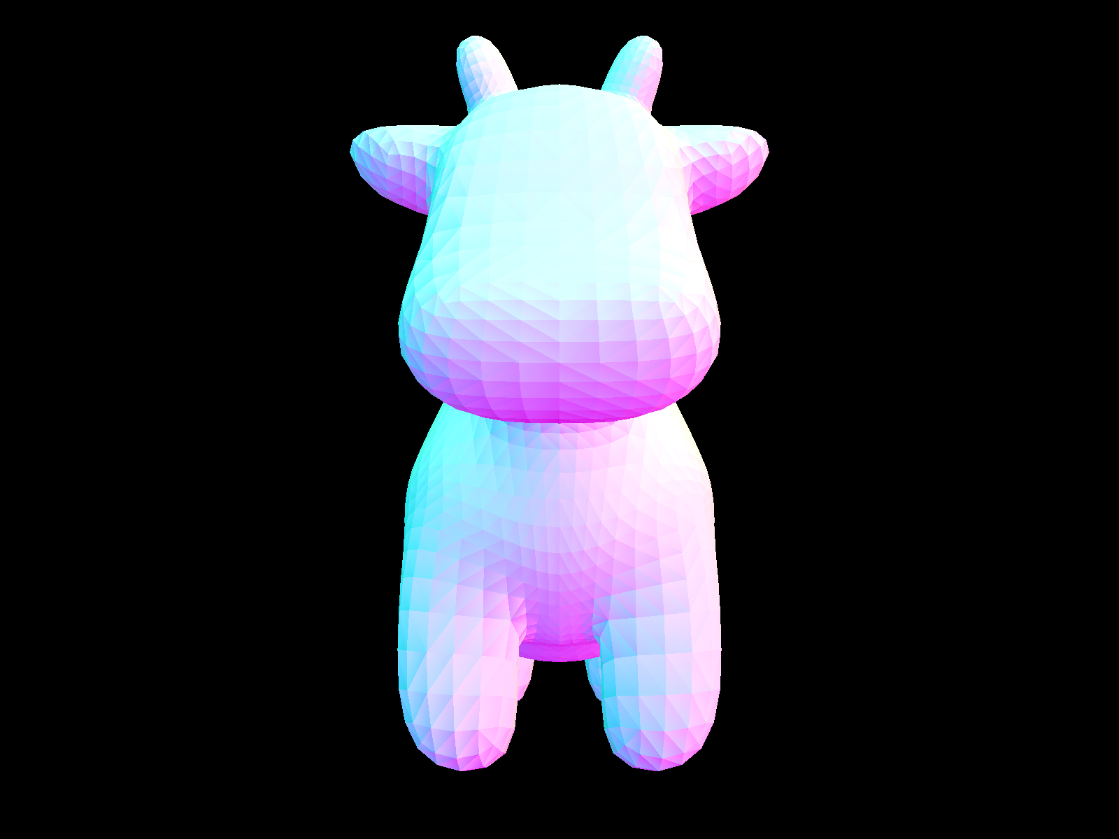
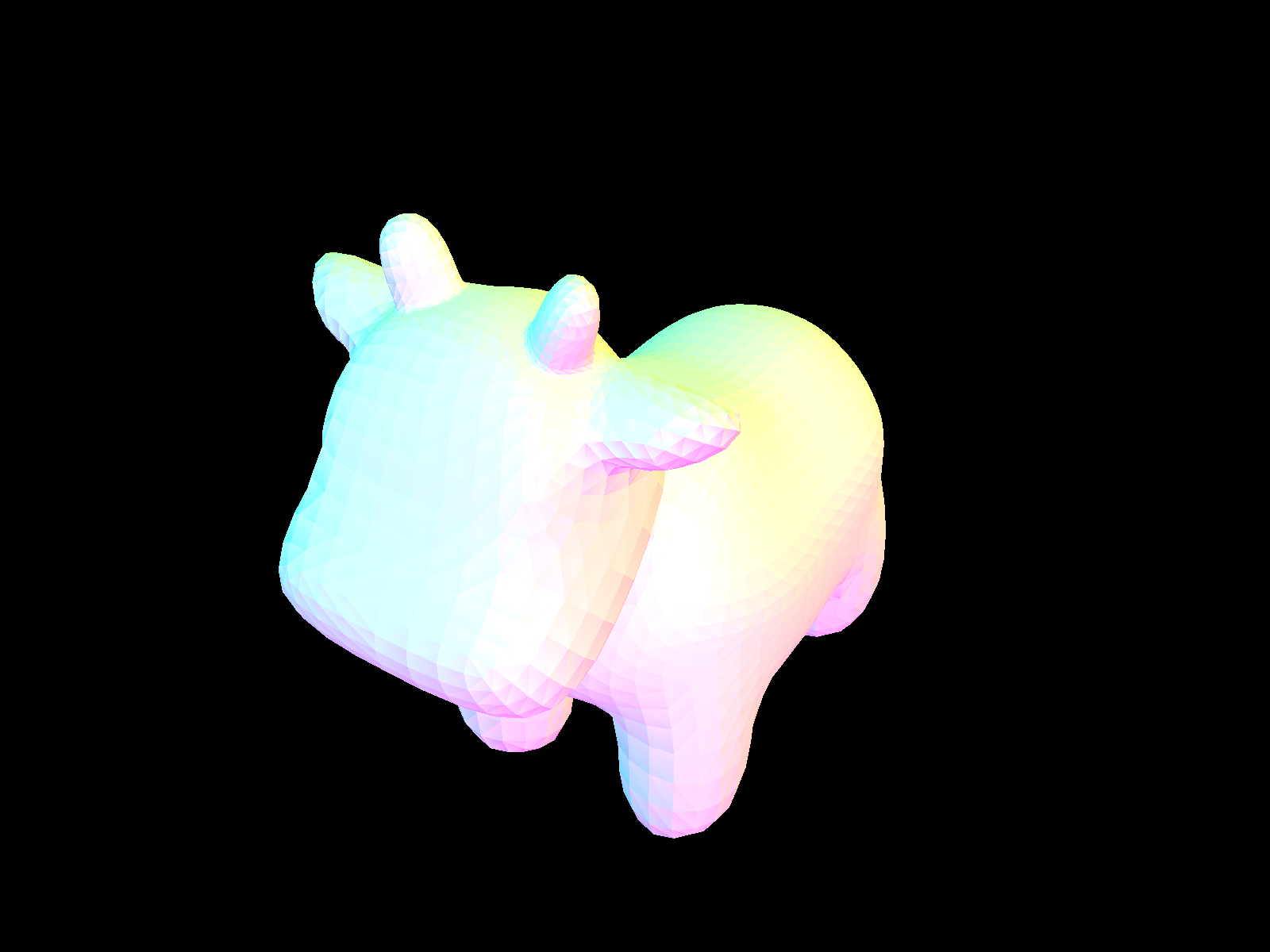
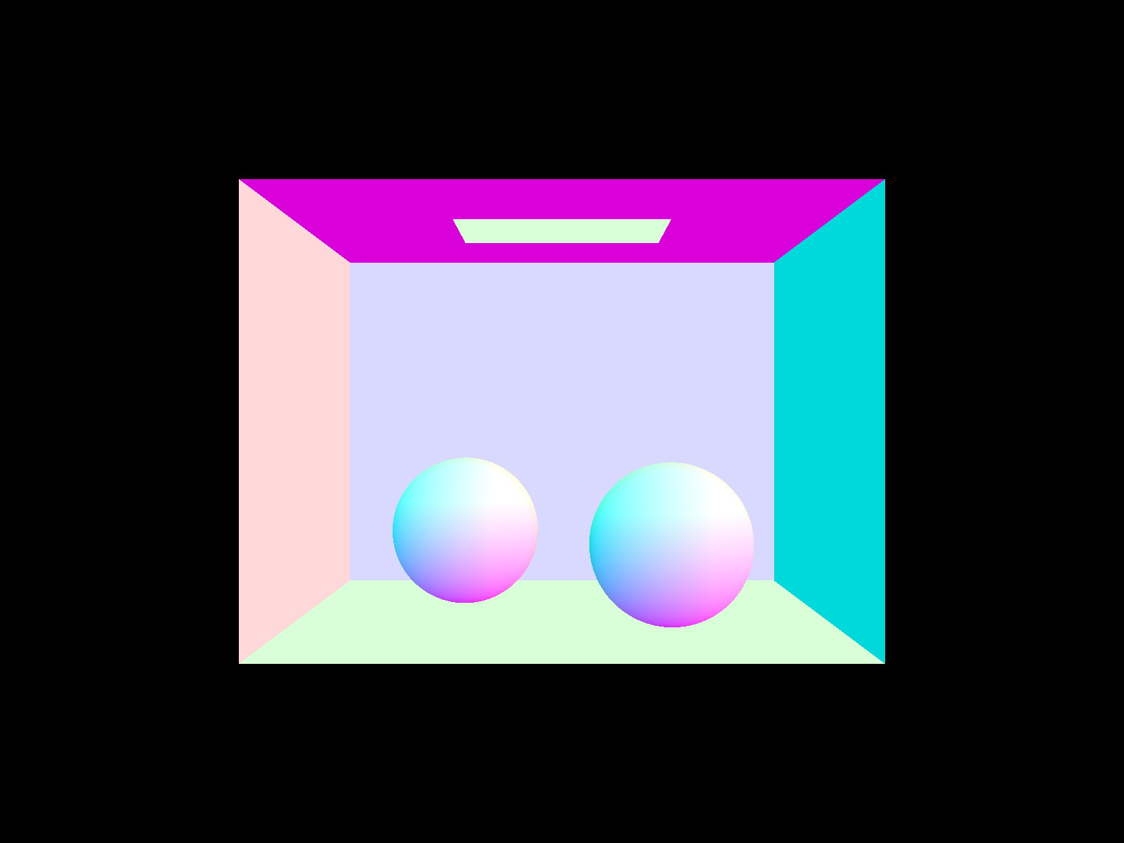
In this part of the project, I wrote code that - for each pixel - creates a number of Ray objects. The number of these objects that are generated corresponds to the user-chosen integer value for samples per pixel.
For each of these rays, I call the method trace_ray() to evaluate the color and brightness "seen" at that location. I then take the average over all of the rays through the current pixel. This will be the color that the user sees on their screen.
A significant detail is how trace_ray() knows what color to return for a particular ray through space. For this part of the project, it simply corresponds to which primitive shape (i.e. sphere or triangle) the ray passes through first, if any. I implemented this separately for the sphere and triangle, using the quadratic formula for the former and the Möller-Trumbore algorithm for the second.
The triangle intersection algorithm I used (Möller-Trumbore) works by converting the point of intersection into barycentric coordinates, then checking whether alpha (b1), beta (b2), and gamma (1-b1-b2) are valid barycentric weights. If so, and if the returned time t is within the acceptable range (so, not behind the camera or too far away), then we say that an intersection took place.
Part 2: Bounding Volume Hierarchy
BVH is an impressive optimization to lower the number of intersection tests necessary. My BVH construction algorithm works by splitting the long list of primitive shapes prims into either the left or the right node of a tree structure. For my heuristic, I chose to split along the longest axis of the centroid bounding box (the smallest possible box that can contain the centroids of all the shapes). That worked extremely well because the most expensive computation occurs when we can rule out the most at once. The longest axis tends to create a fairly balanced tree while grouping together primitive shapes that are actually geometrically close to each other.
The first step of my intersection algorithm is to see whether the ray in question would intersect with any of the bounding boxes. If not, then we can immediately return false. If we have reached a leaf node, then it is time to evaluate all of the intersections with the primitive shapes, ultimately returning the intersection corresponding to the closest one. If we have hit a bounding box but it is not a leaf, then it has left and right children and we need to recurse.
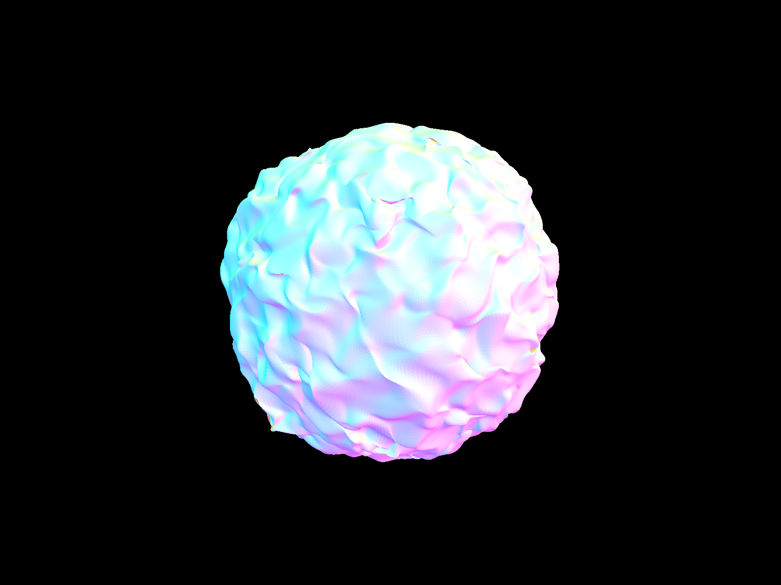
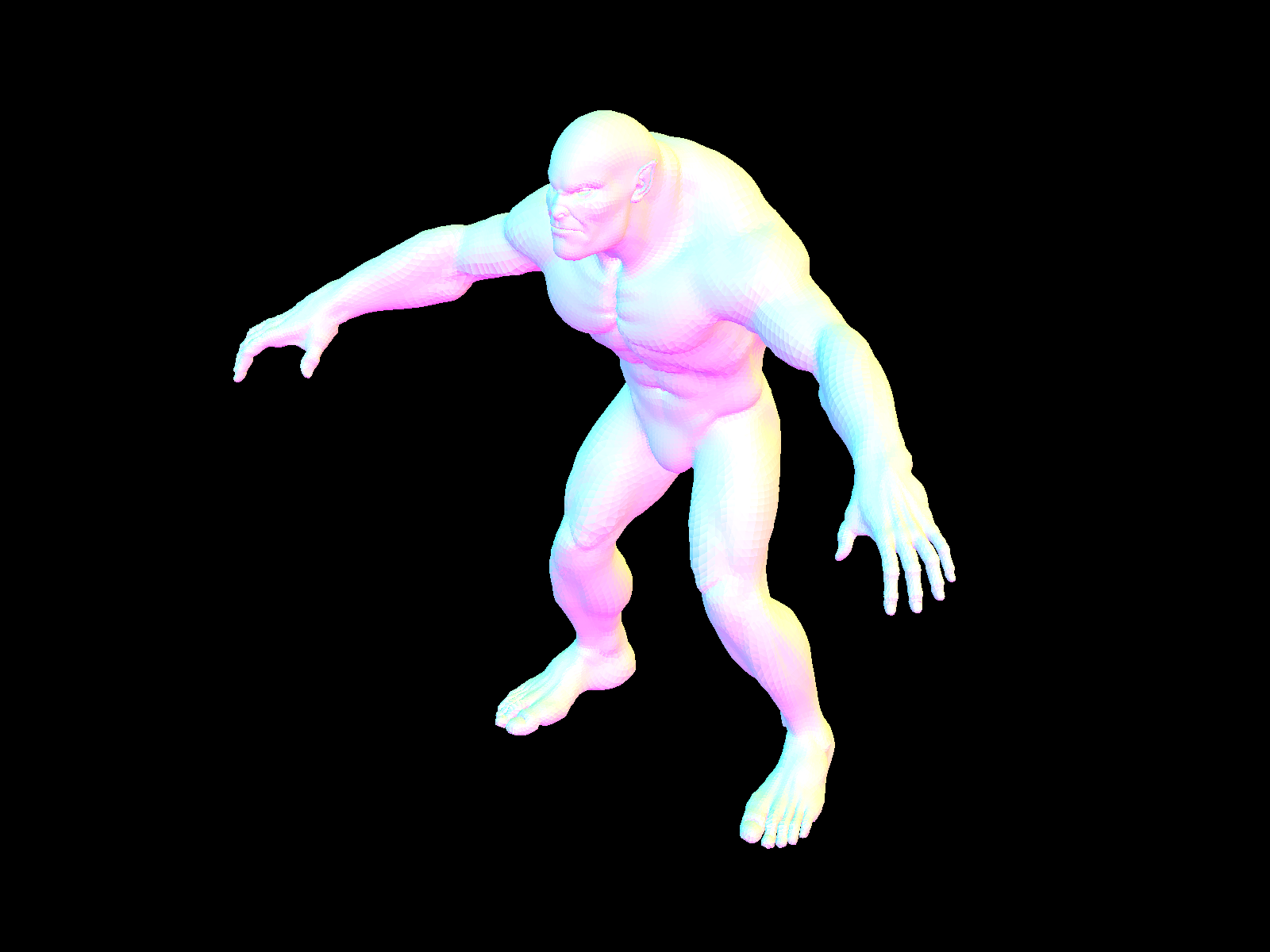
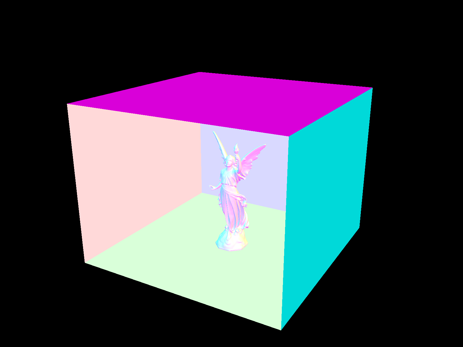
Here are a few .dae files that would not have rendered in a reasonable amount of time had I not implemented the acceleration structure.
Part 3: Direct Illumination
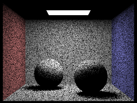
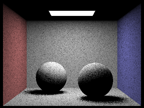
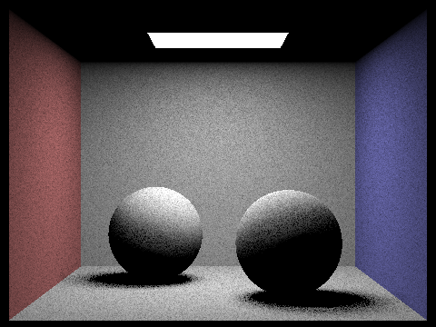
Walk through your implementation of the direct lighting function. Show some images rendered with direct illumination. Focus on one particular scene (with at least one area light) and compare the noise levels in soft shadows when rendering with 1, 4, 16, and 64 light rays (the -l flag) and 1 sample per pixel (the -s flag).
The direct lighting function really helped me to understand what is going on when we "get" light from a light source. Since we are talking about direct lighting (so no bouncing off walls yet) I only needed to iterate over the lights in the scene, which are conveniently available in the data structure scene->lights. In order to "get" the light from the scene to a particular intersection point in the scene, I needed to generate sample rays using another convenient helper, s->sample_L(hit_point). That helper provided the radiance of each ray, along with other useful values. Then to simulate how that light would bounce off of my surface, I had to multiply by the bsdf value that corresponds to each incoming ray.
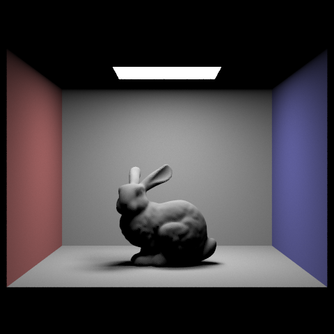
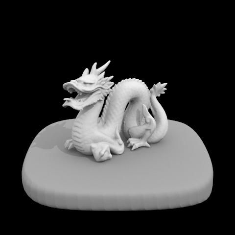
Here are some images reendered with direct illumination. You can see the pretty (and moderately realistic!) shadow.
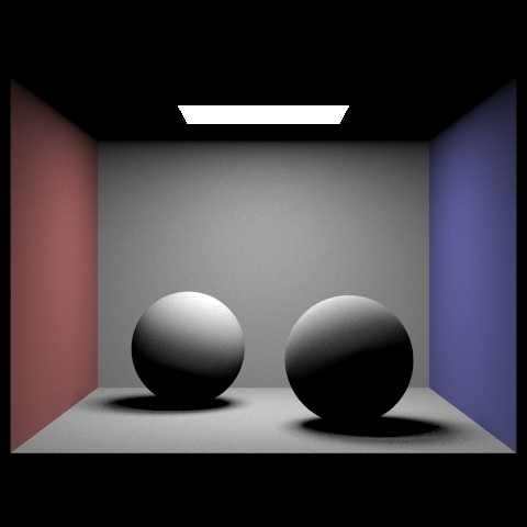
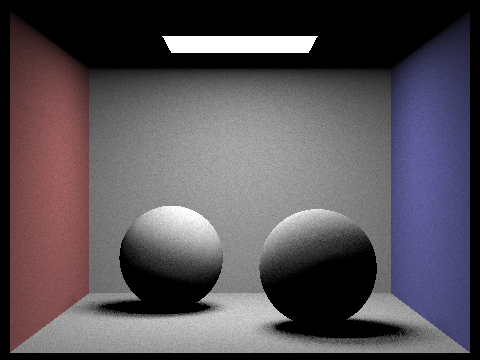
Here are some images with 1, 4, 16, and 64 light rays and 1 sample per pixel. You can see how the noise decreases logarithmically as we increase the number of light rays per intersection point.
Project 3-2: Ray Tracing Part 2
Overview
In this part of the project, I added more interesting materials, environment lighting, and camera simulation. It was very interesting to see how lifelike the lighting becomes once you add camera lens effects and a realistic material. Further, it was very cool to see how probabilistic methods can make sampling much more efficient, requiring fewer samples for the same amount of noise.
Part 1: Mirror and Glass Materials
This part of the project was probably the easiest. The mirror bsdf required so few lines of code! I suppose a perfect mirror is rather simple conceptually so it makes sense.
Glass, on the other hand, was harder to implement because there was a lot of math to implement (most of it derived from Snell's Law) and therefore a lot of places where it was possible to go wrong.
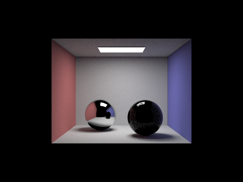
Here is a sequence of six images of scene CBspheres.dae rendered with max_ray_depth set to 0, 1, 2, 3, 4, 5, and 100.
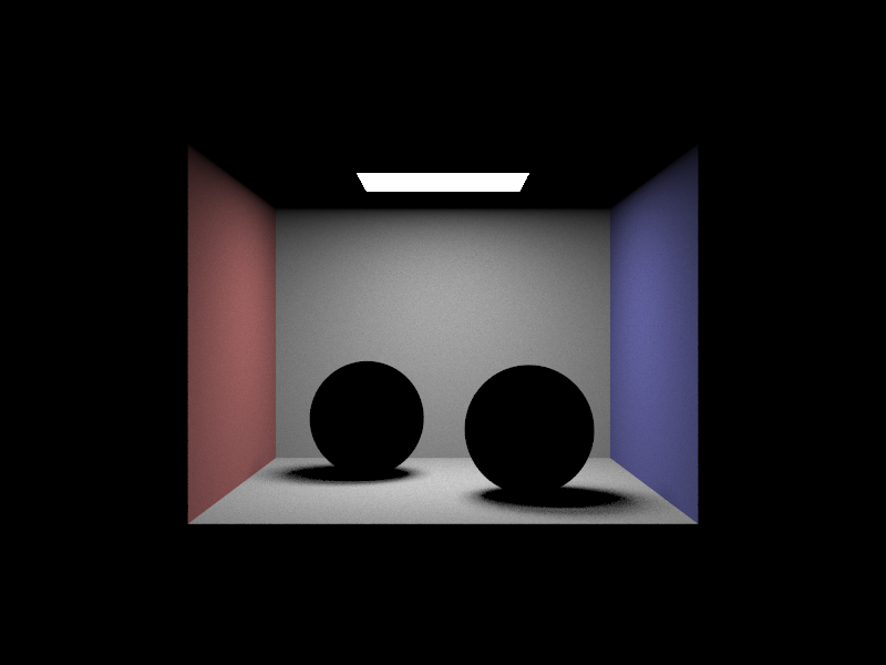
At max_ray_depth = 0, only surfaces directly illuminated by the light have color. Therefore the mirror and glass spheres, as well as the ceiling, appear completely black.
At max_ray_depth = 1, we now see light that reflects off of a surface direcly onto the light. Note that the mirror is working, but the glass ball is still black, since rays are not able to have the minimum 3 bounces to get all the way through to the other side of the sphere and to the wall.
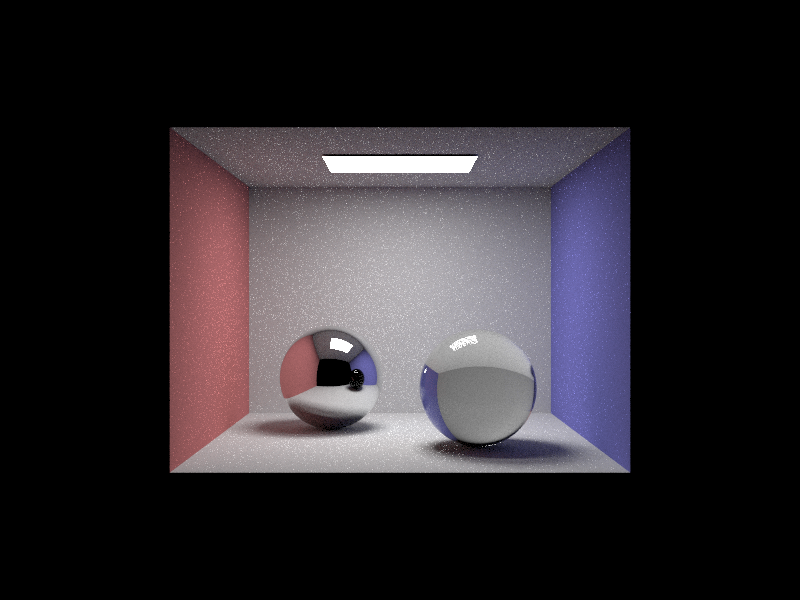
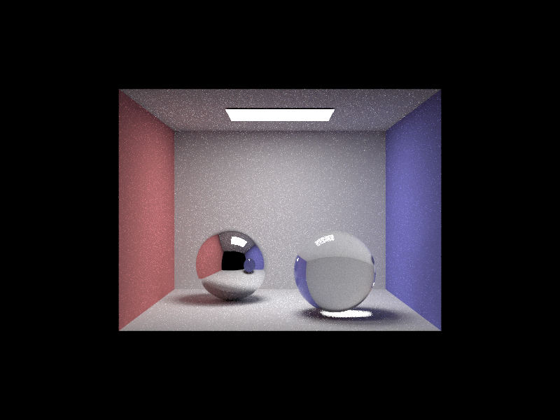
At max_ray_depth = 2, the sphere finally looks alright since rays can go from the camera into the sphere, out of the sphere, and hit the wall. But no light appears to go through the sphere and it appears to give a regular shadow. Also, the mirror reflects what we would see at max_ray_depth = 1.
At max_ray_depth = 3, we now see light going through the glass sphere and illuminating its shadow. That is only now possible because that movement takes a minimum of 4 bounces (camera -> floor -> into sphere -> out of sphere -> onto wall).
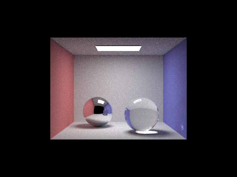
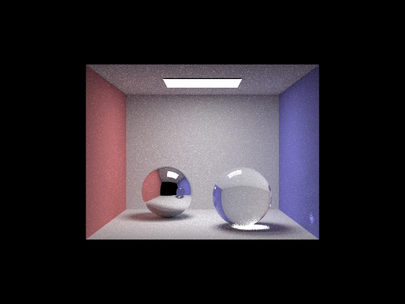
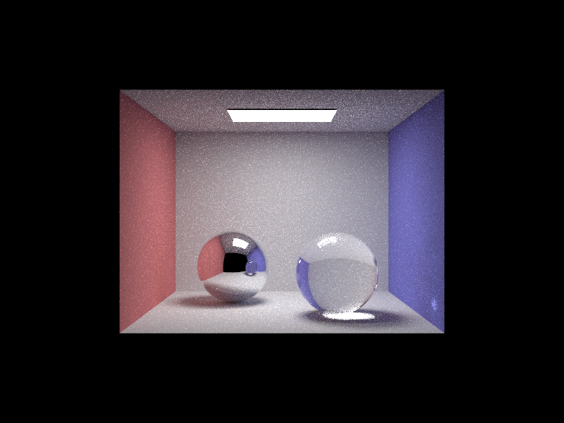
At max_ray_depth = 4, max_ray_depth = 5, and max_ray_depth = 100, light can now reflect off of the mirror sphere and go through the glass sphere from the side. That explains the smaller light patch on the blue wall. Noise seems to increase from 4 to 5 to 100 as well.
Part 2: Microfacet Material
This part of the project was fascinating. It made me really think about what it means for a surface to be glossy or smooth. It wasn't too hard despite having a lot of math to implement, but I got quite stuck on a silly importance sampling-related bug.
Here is a sequence of 4 images of scene CBdragon_microfacet_au.dae rendered with alpha set to 0.005, 0.05, 0.25 and 0.5.
We can see that as alpha increases, the smoothness of the macro surface and the appearance of glossiness both decrease.
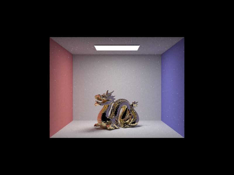
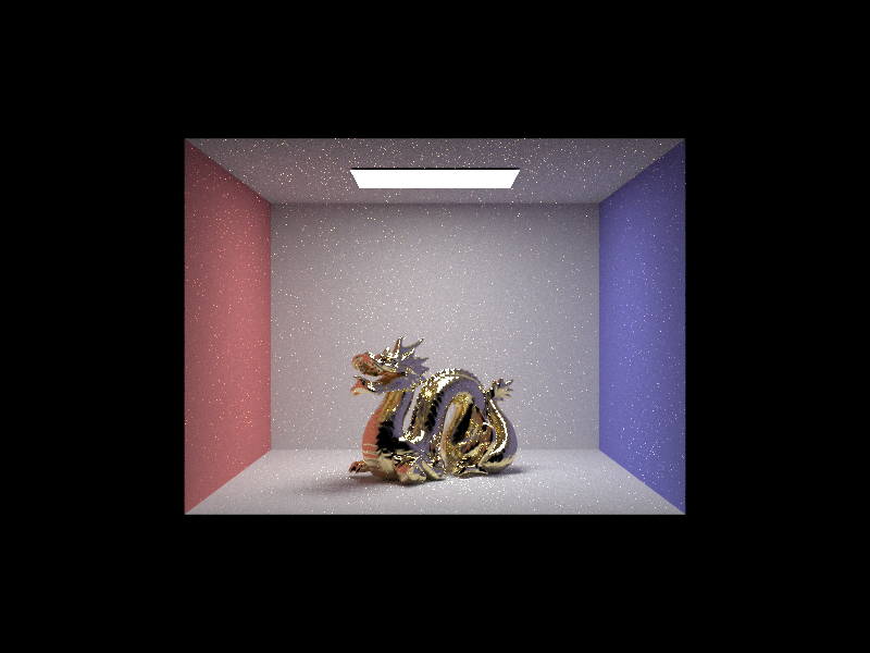
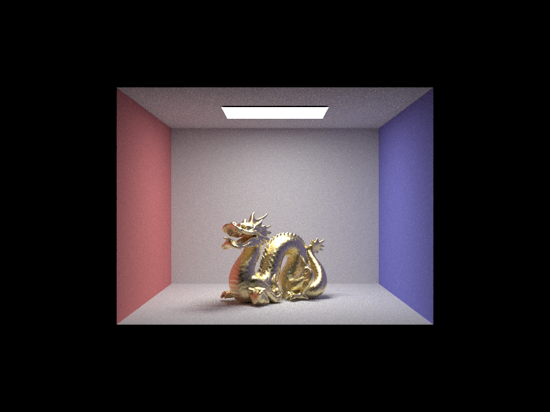
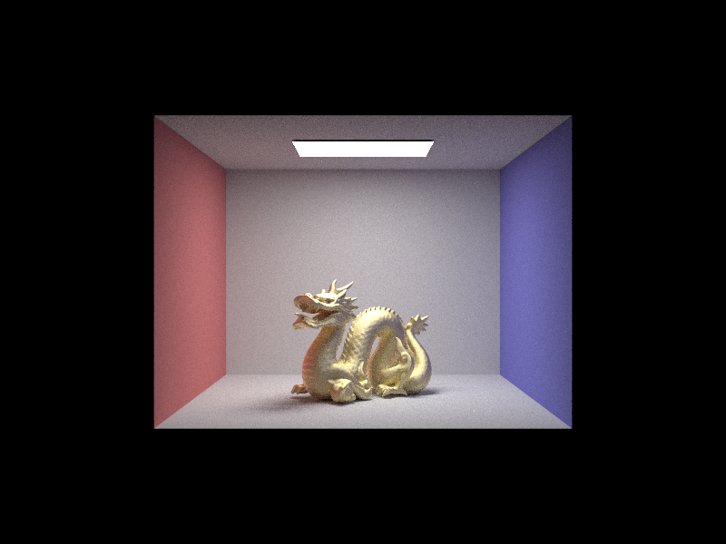
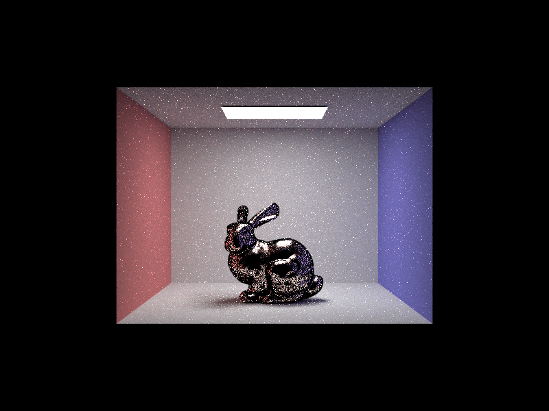
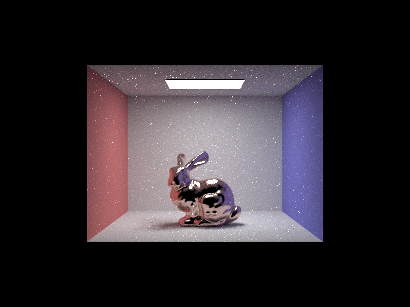
Here are two images of scene CBbunny_microfacet_cu.dae rendered using cosine hemisphere sampling (left) and your importance sampling (right). We can see the significant improvement in noise by using importance sampling.
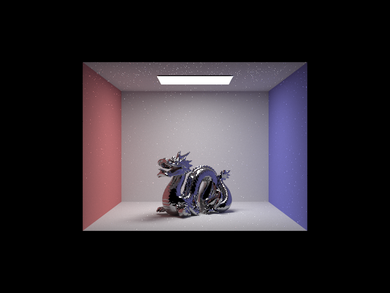
Here is a custom material - titanium carbide: eta = 3.024, k = 2.5945, alpha = 0.005
Part 3: Environment Light
This part of the project was very rewarding. Environment lighting is beautiful. It took me a while to conceptualize the probability distributions and how that probability distribution relates to sampling from an array that represents the lighting plane, but once I understood it I was amazed.
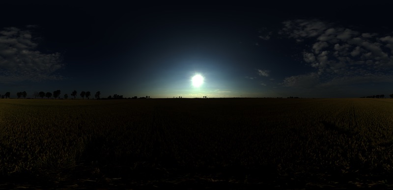
I decided to use field.exr because it's pretty. Here is a .jpg of it:
Below we see bunny_unlit.dae rendered with cosine hemisphere sampling and then importance sampling.
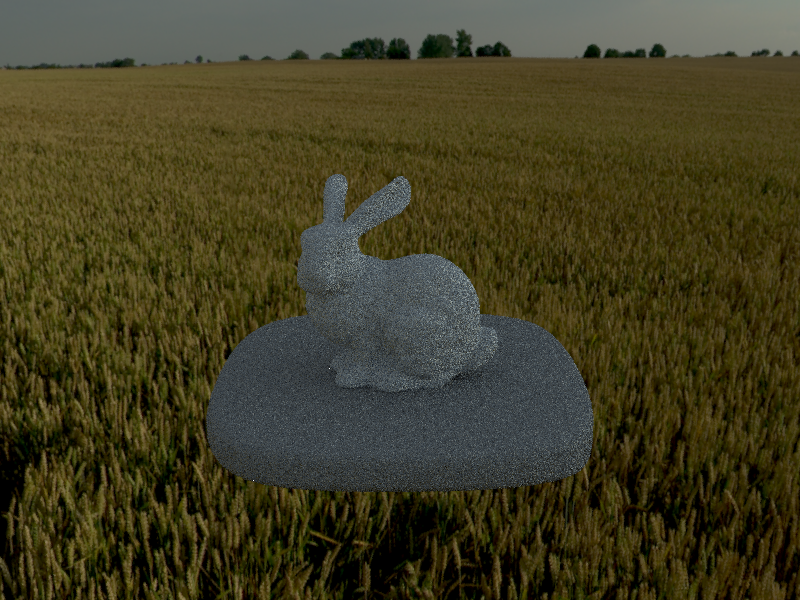
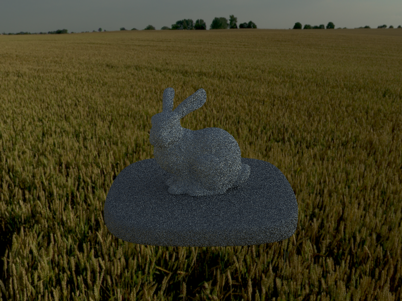
There seems to be rather high noise for both images.
Below we see bunny_microfacet_cu_unlit.dae rendered with cosine hemisphere sampling and then importance sampling.
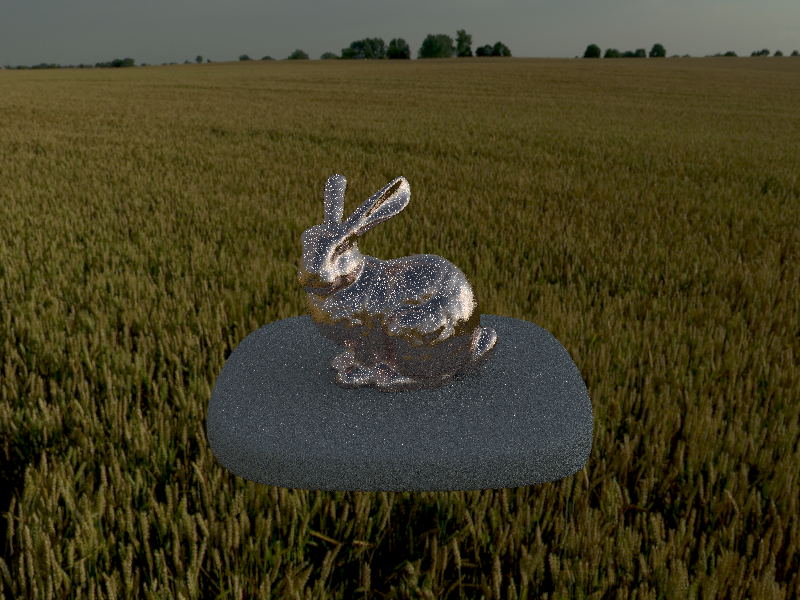
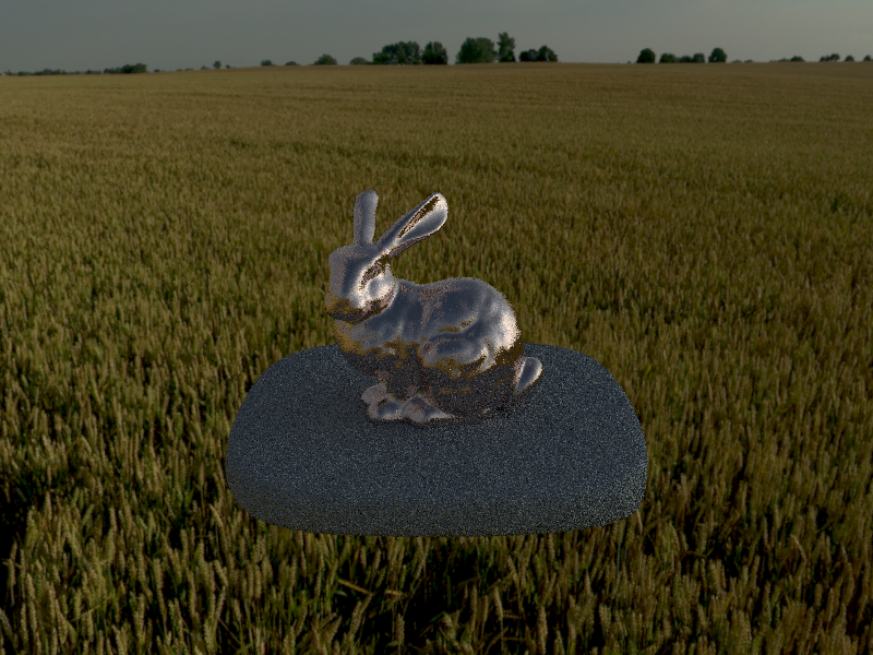
We see that importance sampling has a big impact on the noise level of the environment-mapped image when we have a microfacet surface.
Part 4: Depth of Field
I loved this final part of the project. As a camera enthusiast, it was fascinating to think more deeply about how aperture impacts the depth of field of an image. I had some implementation bugs, as usual, but I located and fixed them. The one that took me the longest to find was a bug where I was doing many samples for each pixel, but only generated one random location on the lens - that generated an unusual result!
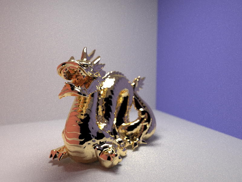
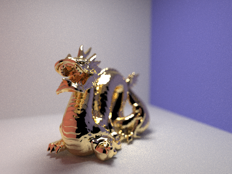
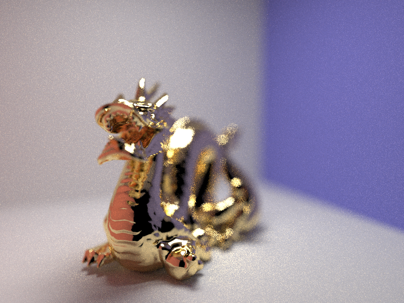
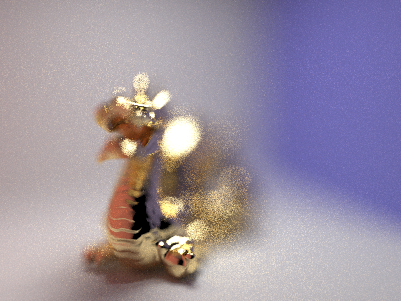
Here is a focus-stack with images at focus level:
1.51.61.71.8
we can see the focus point move back along the dragon.
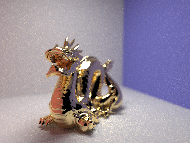
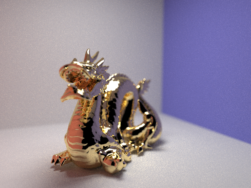
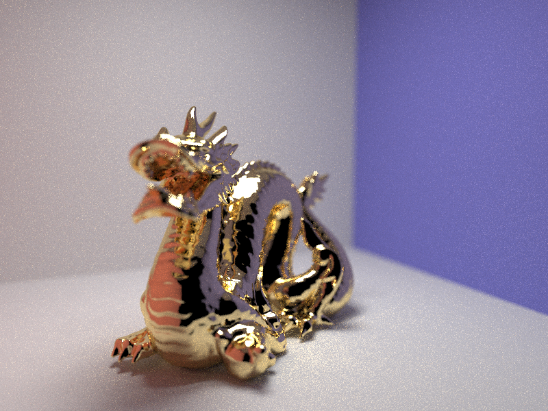
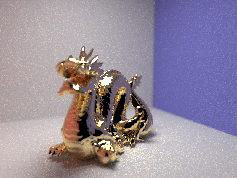
Here is an aperture-stack with images at aperture:
0.150.30.62.4
We can see the image get progressively blurrier as the depth of field becomes shallower.
Conclusion
There is immense satisfaction in generating a realistic shadow beneath a sphere after many hours debugging. The concept of ray tracing is incredibly interesting, but the implementation and debugging process is painfully slow and error-prone. I learned a great deal about C++ in the process of debugging a bounding box error (it turns out that you need to add an epsilon range to doubles when comparing them, since errors cause their comparison to be unreliable).
As always, I'm incredibly grateful to be here at Berkeley learning from and among brilliant people. Graphics is just so interesting and I wish that I had unlimited time in which to learn more.
This class continues to teach me so much about how light really works in the world! It was a pleasure to reason more about glass, microfacet materials, lenses, and probability distributions over planes.
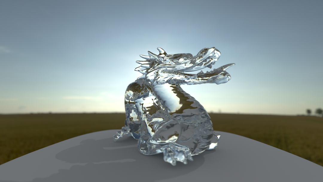
PS: That final image took three days on 8 cores to generate. Click on the image if you'd like to see the full 4k resolution render!